| My Z80 personal computer |
Look HERE for some diagrams of this project.
Starting at the beginning of the 80's I build my own personal computer.
The processor was the brand new Z80 chip, operating at a 4MHz clock speed.
The databus width was 8 bits, the address bus was 16 bits wide.
At that time I had the illusion of being far ahead.
To start from scratch I added a console of LED's and switches.
This allowed access to the memory and starting , stopping or stepping of program execution.
The setting of breakpoints allowed for trouble shooting.
(a breakpoint is an memory address which causes a program halt when referenced)
Programs could be entered manually into the memory.
Manual read or write operations from the console did not need processor halts.
The processor just waited some clock cycles until the console released the bus.
The Z80 processor having 16 address bits could address 65536 bytes directly.
I designed a memory with a size of 512Kbytes.
Bytes $0000 to $c000 (48Kbytes) ware directly addressed by the Z80.($ for hexadecimaal)
Each byte was also addressable in an address window of $c400..$cbff.
This 2Kbyte window worked together with an 8 bit bank register,
so the whole memory could be regarded as 256 banks of each 2Kbytes.
Address window $c000..cfff contained the I/O ports, a midi chip and two video controllers:
one for characters using hardware scrolling and one for graphics with addressable pixels.
The console resolution was 480 x 250 pixels. Two bits per pixel allowed for 4 grey scales.
A text page was 25 lines of each 80 characters maximal.
Address space $D000 ..$FFFF contained 3 EPROMS of each 4Kbyte.
These EPROMS contained diagnostic programs and a simple operating system
with drivers for a tape cassette and a floppy disk.
It also contained a program to burn EPROMS.
A tric allowed for starting the processor at address $D000 after reset.
Pressing RESET while another switch was UP did set the HI-start FlipFlop.
This FF forced address bits to $Dxxx.
These bytes ($D000,$D001,$D002) contained a jump instruction to $D003
and reading this instruction cleared the HI-start FlipFlop.
I/O was performed by 6 parallel channels, each bidirectional and 8 bits wide.
Additional to 8 data lines there were 4 function- and 4 status lines.
The function lines allowed for control of the peripheral equipment.
Controllers for the tape-cassette, floppy disk and keyboard were housed in an external box.
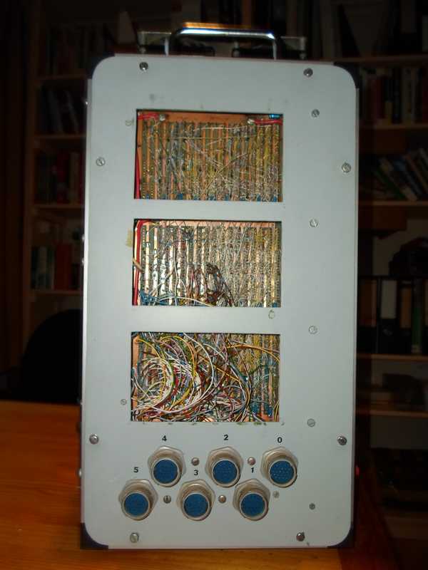
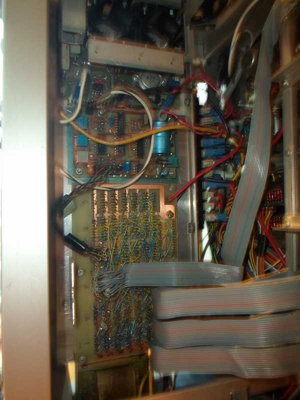
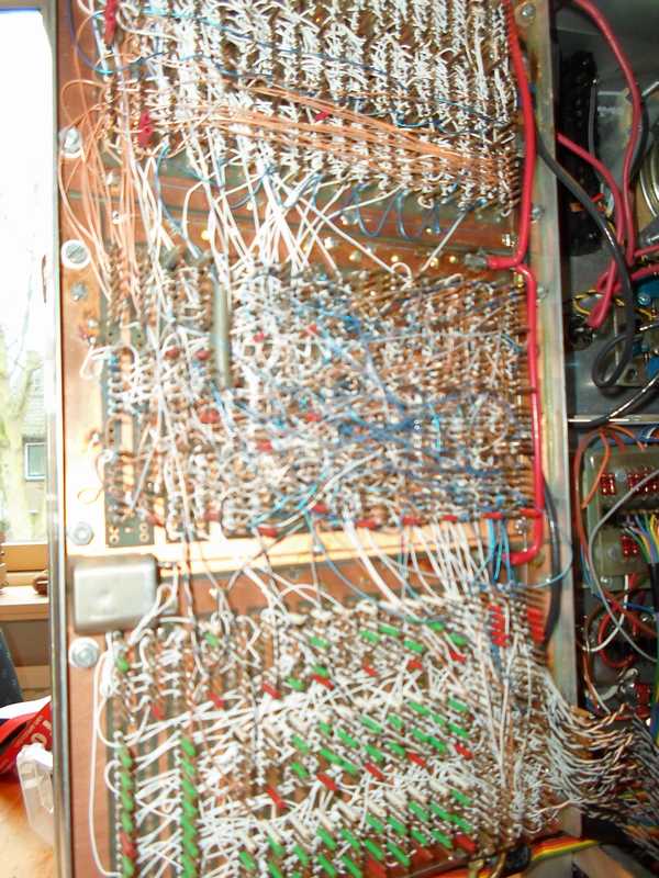
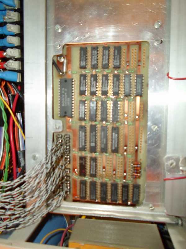
In total the project used some 400 TTL chips.
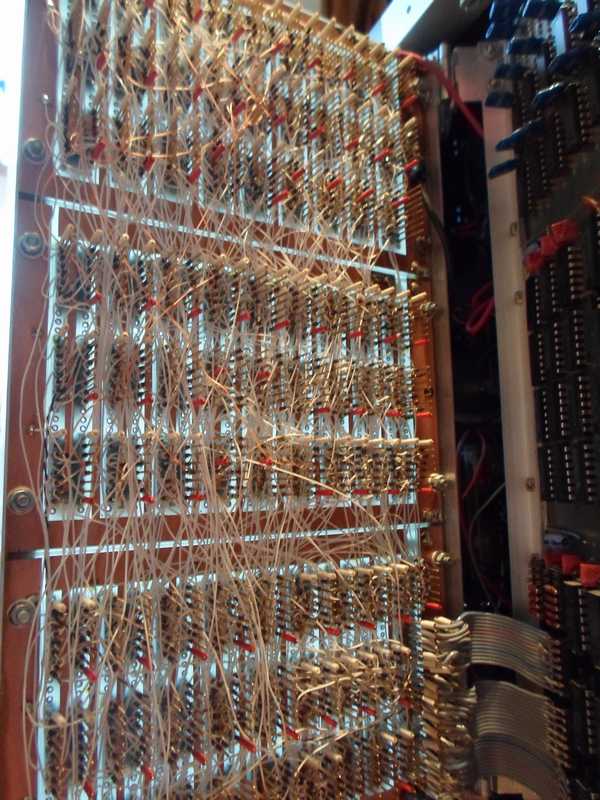
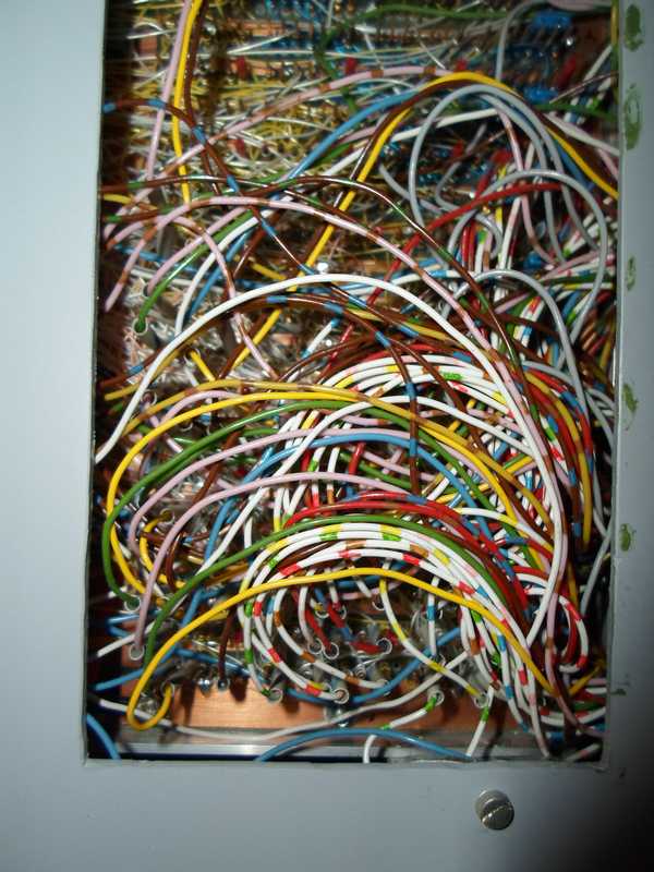
These were mounted in wire-wrap sockets for simple replacement and modification.
Flat cable and DIL plugs made the bus connections.
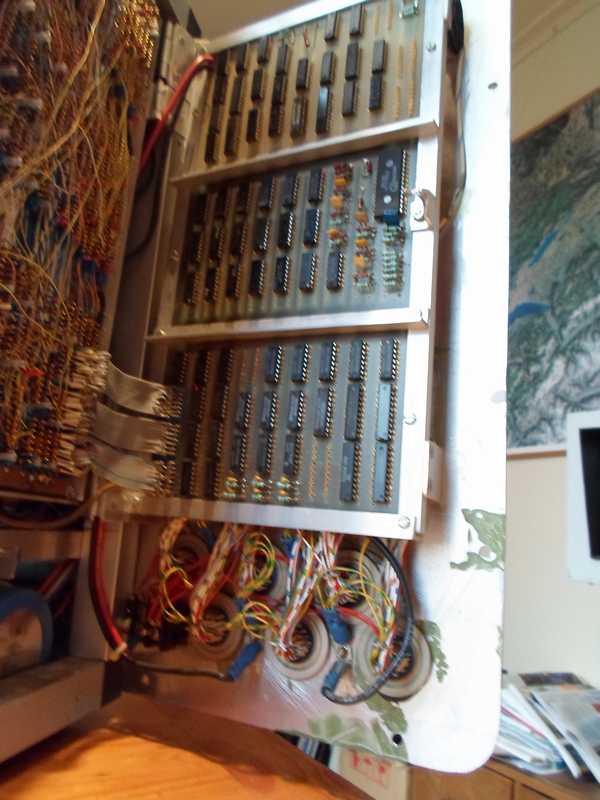
Three standard prints of each 27 chips made a frame.
The four frames were attached to the chassis by hinges for easy access.
The graphical video controller was added later as the fifth panel in the (fixed) center of the cabinet.
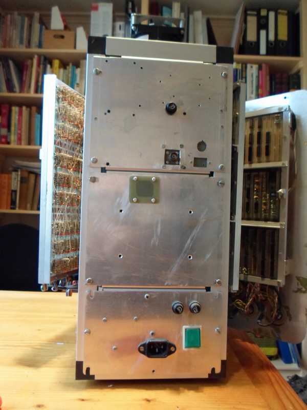
The bottom housed the power transformers and regulators (5 and 12 volts).
On the top were two blowers in series (American, 115 volt each).
At completion this machine was already a museum piece.
Below are some pictures:
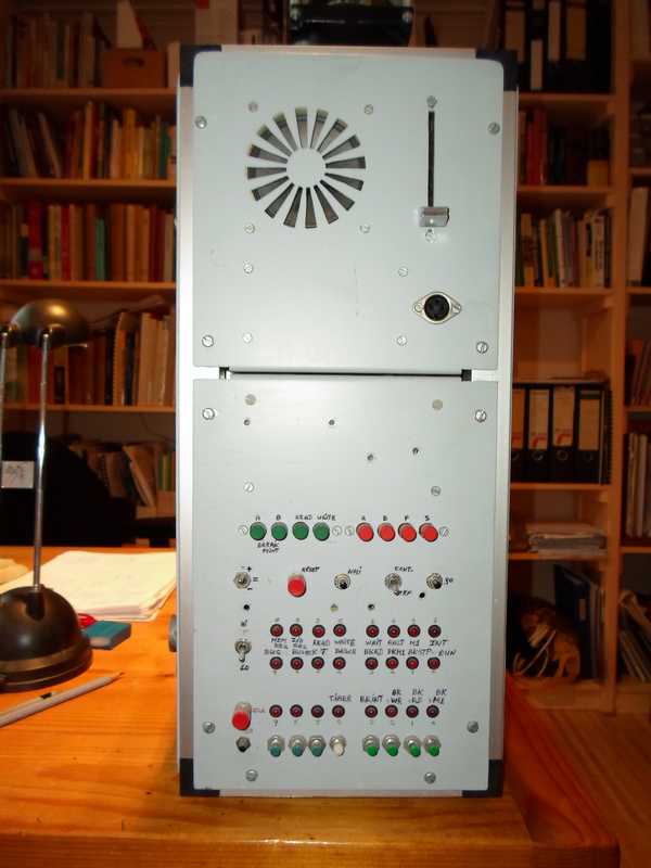
Buttons for start-stop, read and write and breakpoints.
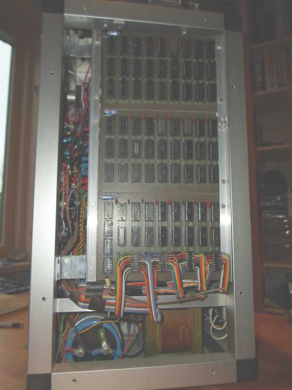
Right below the flat cables for bus signals.
The block diagram of the panels
(1,2 right turning; 3 fixed; 4,5 left turning)