

| Bitmap magnification by interpolation |
Introduction
The Delphi TBitmap class has a two dimensional array of bytes,words or cardinalscalled the canvas which holds an image.
An individual byte,word,cardinal of this canvas is called pixel.
In many occasions, images need to be resized.
This may be done by copying the bitmap to a new one of different size,
using a suitable algorithm to calculate the pixel values of the new bitmap.
One method is to take the individual pixels from the destination bitmap,
project them over the source pixels and calculate the average color of the source pixels covered.
I call this the "projection method".
Look here for a description of the projection method for bitmap resizing.
This method works fine in case of image reduction.
For images enlarged by a factor 2 or 3, the result is not smooth.
In this article I describe a better algorithm for these cases:
-
- transfer the source pixels directly to their new position in the destination bitmap
- use interpolation to calculate the remaining -in between- pixels of the destination bitmap
See the next pictures showing the different resizing algorithms for a three fold magnification:
 |
 |
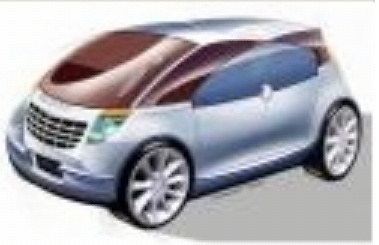 |
| original image | projection method | interpolation method |
Use a magnifying glass to see the differences more clearly.
TBitmap class
In this project, pixels are cardinals only (unsigned 32 bit integers).This is the internal layout of a 32 bit pixel:

There are 8 bits per color, color intensity ranges from 0 to 255.
Bits 24..31 are not used.
Next picture shows the coordinate positions of the pixels.
The scanline[y] property supplies the pointer to the first pixel of row y.
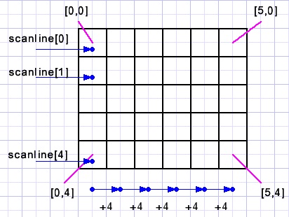
Pixels on the canvas of bitmap map are addressed by: map.canvas.pixels[x,y]
This is a slow process, only suitable for a few individual pixels.
Many (50) times faster is to address pixels by a pointer to their memory location.
To facilitate pointer calculations I store these pointers as dwords.
Next a bitmap named map is created with 100 rows and 200 columns:
type PDW = ^dword;
...
var map : TBitmap;
    p0  : dword;//pointer to [0,0]
    pstep : dword;//pointer distance between rows
....
begin
 map := TBitmap.create;
 with map do
  begin
   width := 200;
   height := 100;
   pixelformat := pf32bit;
  end;
  p0 := dword(map.scanline[0]);
  pstep := p0 - dword(map.scanline[1]);
Now the expression
color1 := map.canvas.pixels[12,75]; //----1can be replaced by
color1 := PWD(p0 - 75*pstep + (12 shl 2))^; //------2Note:
In cases -1- and -2- before the values of color1 are different.
In case -1- the red field occupies bits 0..7, blue 16..23.
This is the Windows color format for 32 bit and 24 bit pixels.
Regarding a 100*200 pixel bitmap as a one-dimensional array[0..19999] of dword,
the first dword [0] is at pixel position [0,199], the left bottom.
Dword [1] is at pixel position [1,199] which is 4 bytes higher.
Going from [0,199] to [0,198] requires addition of 4*200 = 800 to a pointer.
Pointers are byte adresses.
Expression (12 shl 2) is a fast way to multiply 12 by 4.
For a next row, a pointer has to be subtracted by value pstep = 4*column count
Note:
Regarding a bitmap as a one dimensional array A,
the pointer to A[0] is bitmap.scanline[bitmap.height-1].
Multiplication by 2
A 5*5 bitmap is magnified to 10*10.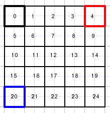 |
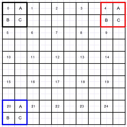 |
The pixels that are directly copied are indicated by a number.
Next the -in between- pixels A,B,C have to be calculated.
The bottom row and also the right column need separate action.
The project
Please refer to the source code.
There are 2 units, -1- provides control and event handling.
The expansion_unit holds the procedures for the pixel processing.
First, unit-1- has to load the image.
.bmp or .jpg images may be loaded in bitmap map1.
map1 is made visible in paintbox1.
bitmap map2 is created with 2x the width and 2x the height of map1.
Then procedure X2copy(map2,map1) is called to perform the magnification.
procedure X2copy
type TAIP = arry[1..8] of dword;
var c1,c2,c3,c4 : dword; //colors of source map
    AIP : TAIP;          //interpolation pixels
    pd0 : dword;         //destination row 0 pointer
    pd1,pd2 : dword;     //destination row pointers
    pdstep : dword;      //destination row difference
    ps0 : dword;         //source row 0 pointer
    psstep : dword;      //source row difference
    x,y : word;          //source pixel addressing
    py,py1 : dword;      //scratch pointers
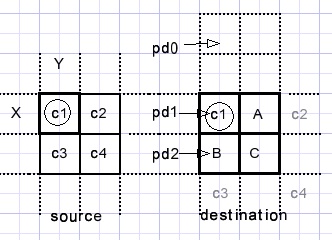
Pixels are processed starting left top to right bottom.
variables x,y address the source pixel c1 {c stands for color}.
C1 is copied directly to the destination bitmap.
To calculate the in-between pixels A,B,C the
procedure interpolate24(AIP,c1,c2,c3,c4); is called.
A is AIP[1]
B is AIP[2]
C is AIP[3]
Interpolate24...{2x magnification, 4 variables} calls
procedure unpackColor(var r,g,b : byte; col : dword);
begin
 b := col and $ff;
 col := col shr 8;
 g := col and $ff;
 col := col shr 8;
 r := col and $ff;
end;
which extracts the 8 bit r,g,b values from dword col.
c1 has r1,g1,b1 values for red,green, blue.
c2 has r2,g2,b2 values...etc.
Then r,g,b values are calculated for each A,B,C color.
A = (C1+C2)/2 for r,g,b
B = (C1+C3)/2 for r,g,b
C + (C1+C2+C3+C4+3)/4 for r,g,b
Finally r,g,b colors are packed in AIP[1], AIP[2}..etc by a call to
procedure PackColor(var col : dword; r,g,b : byte);
begin
 col := ((r shl 16) or (g shl 8) or b);
end;
Please refer to the source code for details.
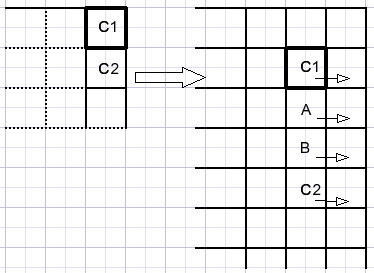
Right column
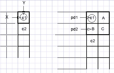
Pixel c1 at [x,y] is copied to the destination bitmap.
Pixel A is equal to c1.
Pixels B and C are the average of c1 and c2 which is calculated by
procedure interpolate22(var AIP : TAIP; c1,c2 : dword);
//return AIP[1]
var r,g,b,r1,g1,b1,r2,g2,b2 : byte;
begin
 UnpackColor(r1,g1,b1,c1);
 UnpackColor(r2,g2,b2,c2);
 r := (r1 + r2) shr 1;
 g := (g1 + g2) shr 1;
 b := (b1 + b2) shr 1;
 packcolor(AIP[1],r,g,b);
end;
Bottom row
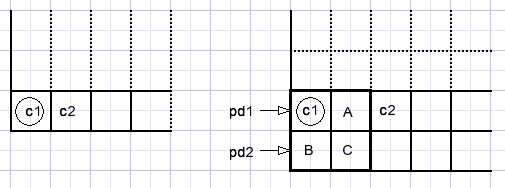
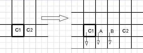
c1 is copied from the source bitmap.
B equals c1.
A and C are the avarage of c1,c2 calculated similar to the right column pixels.
Multiplication by 3
Below is pictured a 3x4 bitmap and it's magnification by 3.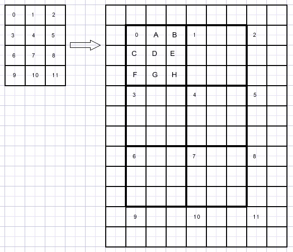
The proces is similar to the x2 magnification however more calculation is required.
First the 3x3 pixelfields in the destination bitmap are processed.
Interpolation is more complicated.
I calculate pixels A,B,C,D,E,F,G,H as weighted average of C1,C2,C3,C4.
If a color (C1,C2..) has distance d to a pixel (A,B,C...) it's weight factor w = 1/d.
The Pythogaras lemma is used to calculate the distances.
A = (1.C1 + 0.5C2)/(1+0.5) = 0.66C1 + 0.33C2
B = (0.5C2 + 1.C1)/(1+0.5) = 0.33C1 + 0.66C2
D = 0.36C1 + 0.23C2 + 0.23C3 + 0.18C4
Please look at the next picture:
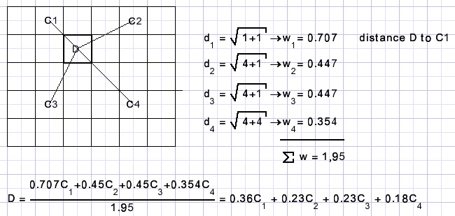
Of course the calculation for D is repeated 3 times: for red, green and blue.
Right column
C1C2 and interpolation colors A,B are copied also to the far right destination column.
Bottom row
The C1 and C2 values are copied directly.
A,B are interpolation colors.
C1,C2,A,B are copied to the bottom row of the destination map.
Showing results
map1 (loaded from disk, is displayed in paintbox1.Paintbox1 has a fixed size of 400*400 pixels.
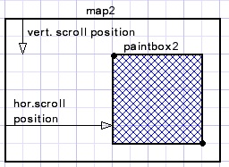
map2 is the result of expansion and this bitmap is displayed in paintbox2.
This paintbox is 800*800 pixels in size.
To show all pixels in case map2 is larger, horizontal and vertical scrollbars are added on form1.
The scrollbar max property has to be adjusted for the size of map1.
The following code takes care
var d : smallInt;
...
begin
 d := map2.width - paintbox2.Width;
 if d < 0 then d := 0;
 Hscrollbar.max := d;
 Hscrollbar.position := 0;
 d := map2.Height - paintbox2.Height;
 if d < 0 then d := 0;
 Vscrollbar.Max := d;
 Vscrollbar.position := 0;
end;
A scrollbar onChange event calculates the rectangle to be copied from map2 to paintbox2:
procedure TForm1.VscrollbarChange(Sender: TObject);
//V,H scrollbar changes
//repaint paintbox2
var BW,BH : word;//paintbox width,height
    rs,rd : Trect; //source,destination rect
begin
 BW := paintbox2.Width;
 BH := paintbox2.Height;
 with rs do
  begin
   left := Hscrollbar.position;
   top := Vscrollbar.position;
   right := left + BW;
   bottom := top + BH;
  end;
 with rd do
  begin
   left := 0;
   top := 0;
   right := BW;
   bottom := BH;
  end;
 paintbox2.Canvas.CopyRect(rd,map2.Canvas,rs);
end;
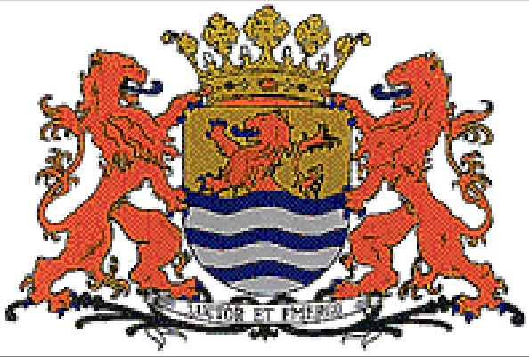
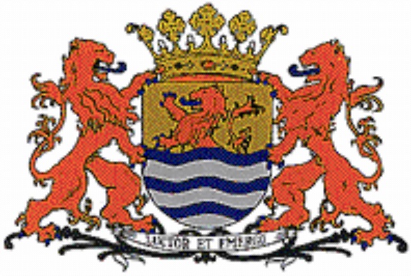
To conclude I show another example of a 3 times magnified image using both the projection
and the interpolation method:
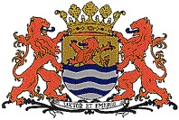
original image:
projection method:
interpolation method:
The image represents the escutcheon of the Dutch county of Zeeland.
A somewhat free translation of the text (Luctor Et Emergo) is : "pump or drown".

