

| H(ro)Bot simulator |
Introduction
Pictured below is a Hbot : H shaped robot.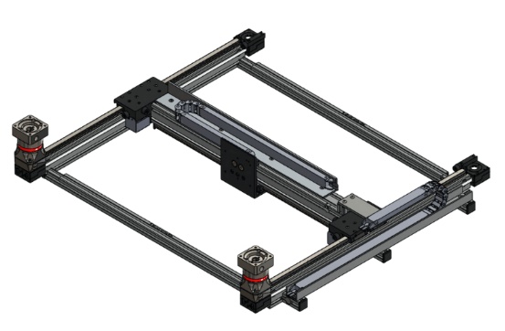
This article describes a HBot and a siulator program. See (reduced picture) below:
The robot is implemented as a plotter.
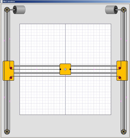
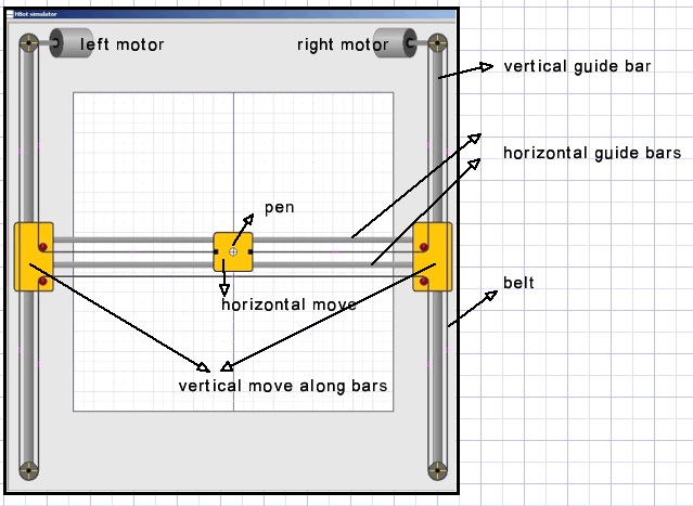
At the left and right top are two fixed motors operating independently and driving a single belt.
As the motors rotate clockwise or counter clockwise, the pen moves in a horizontal , diagonal or vertical direction.
Parts
There is one single belt which ends are attached to the pen.
Theory
Vertical pen movement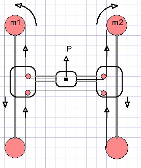
Motor 1 moves counter clockwise, motor 2 moves clockwise, the same distance.
Pen P moves upward.
Horizontal pen movement
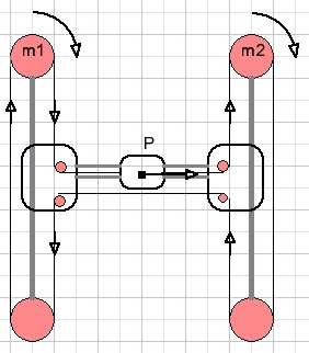
Motor 1 moves clockwise, motor 2 also moves clockwise, the same amount.
PenP moves horizontally to the right.
Diagonal pen movement Is the result of both vertical and horizontal movement.
For pen
Up    = Left motor CCW  d; Right motor CW d (distance)
Right = Left motor  CW  d; Right motor CW d
---------------------------------------------------------  add actions
Diagonal UP =  Right motor CW 2d
Diagonal right up movement by distance d is the result of a 2d distance turn by motor 2.
The motor 1 movements cancel each other.
Summarizing:
For diagonal movement only one motor moves.
The belt movement is doubled: it is the sum of horizontal and vertical movement.
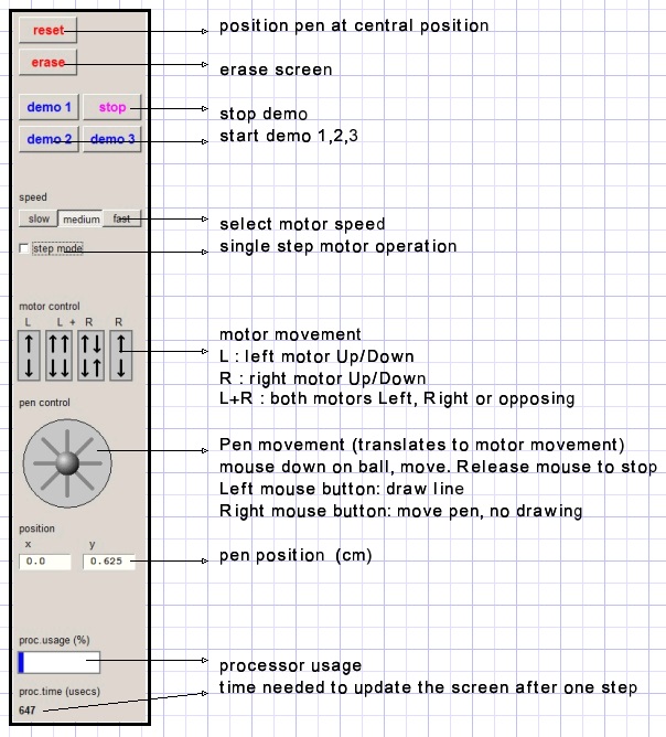
Simulator usage, buttons and indicators
The simulator program
General considerations-
- Movement must be realistic: smooth without flickering
- Moving parts must be visible as such
- Buttons must show the principle of operation
However, this is not sufficient because erasing the picture before drawing the updated situation
causes irritant flickering. This is avoided by assembling the HBot in a bitmap (mapX) and using
copyrects to transfer changed areas of mapX to paintbox1.
Some areas of the screen are painted once and do not change.
This background is painted in mapA.
Parts of A are transferred to mapX. Also the pen draws in mapA.
Moving wheels have attached spokes or a line mark to indicate movement.
Purple dots are painted on the belt to show movement.
Timing
Updating the screen after a (one pixel) move takes some time.
This time is displayed.
After updating the screen the processor has to wait for a certain time for the required speed.
A blue bar displays the percentage of time needed for a one pixel update.
Typical time is less than 800 microseconds.
Areas and bitmaps
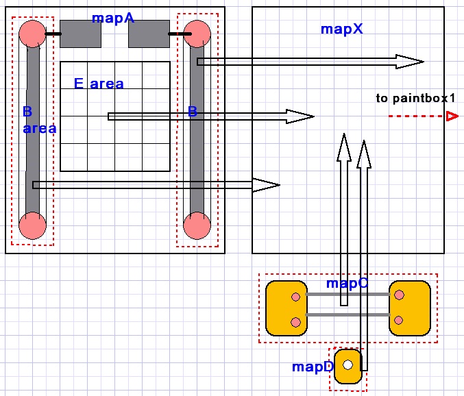
MapA : bitmap with motors and B areas with vertical guides, wheels and belt.
Area E is for drawing and shows a coordinate system.
MapA is copied to mapX.
Map C: bitmap holding horizontal guide bars and wheels and is copied to mapX.
MapD : pen holder. Is copied to mapX.
MapX is (partial) copied to paintbox1 to become visible after adding spokes to the wheels and adding dots to the belt.
Delphi code
For details, please refer to the source code.
Units
-
- unit1 : simulator control, constants, variables, painting procedures.
- Unit2 : TDav7ELbox is a Tpaintbox with enter leave events added and is
used for motor control buttons.
- Timer_unit: code to turn CPU ticks into a microseconds clock for speed control.
- Demo_unit: supplies 3 demos to illustrate HBot operation.
PaintmapA, paintmapC, paintmapD,paintLeftMotor,paintRightMotor : self explanatory.
PaintB : paint area B on mapA.
PaintE: paint coordinate system on mapA.
procedure paintchain(mp: Tbitmap;x1,y1,x2,y2 : word);// paint belt on bitmap mp (x1,y1)--> (x2,y2)
XpartialToBox; //area of mapC, B areas --> paintbox, these are the updated rectangles of mapX
procAWheelmovement; //place spokes on wheels in B areas.
procCwheelmovement;//add spoke to small wheels in C area.
procBeltMovement;// add purple dots on belt
For the last three procedures, the place of the spokes or dots is calculated from the position of the pen.
(0,0) is the center of area E.
The coordinates on E are (-320,-320) left top to (320,320) right bottom.
The procBeltMovement code is lengthy because the belt is divided into horizontal and vertical stretches
and also the arcs around the wheels.
Moving the pen
This simulator project is for educational purposes.
For that reason there are two ways to move the pen:
-
1. By controlling the motors and observe pen motion.
2. By controlling the pen and observing the motors.
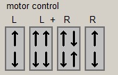
Picture above shows four paintboxes with added on-enter and on-leave events.
Code is provided by unit2. These paintboxes are created at run time.
A left mouse button down on the top half of the L button moves the left top motor counterclockwise.
The bottom half causes clockwise motion.
These actions reverse for the right mouse button.
The R paintbox operates in a similar way, now causing clockwise motion for a mouse button down on the top part.
The L+R buttons activate both motors moving either in the same or in opposite directions.
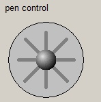
To move the pen without drawing:
Right mouse button down on the sphere, move in chosen direction.
Release mouse button if pen reaches position.
Use left mouse button to move the pen for drawing.
A mouse down event on the sphere causes the movebusy flag to set.
The movebusy flag enables mouse move events.
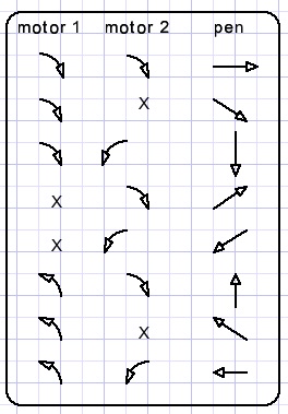
The pen control paintbox is divided in cells, the cell number is translated to the direction code (xdircode).
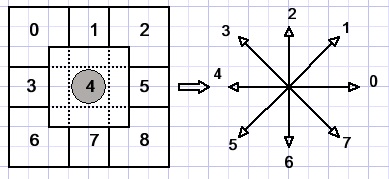
Left pictured are the paintbox cells and right the direction code is displayed.
Procedure procXpainting is called which sets the moveflag and continuously calls procedure procmove as long as the moveflag is set.
Procmove takes care of the speed. For single motor operations, the time out period is doubled because
the motor has to turn twice the distance moving the pen in a diagonal way.
Procmove calls procedure moveControl to calculate the new pen position (penPosX,penPosY),
update mapX and copy parts of mapX to paintbox1 on form1.
If outer bounds of the E area are reached procMove clears moveFlag and pen motion stops.
The demo unit
Three demos are provided. The demo buttons have tags 1..3 and share the OnClick event.A demo button click calls procedure startdemo(demoNr).
Demo 1:
Plots the parameter function
-
X = 150(sin(8t)+sin(t))
Y = 150(cos(8t)+cos(t))
For each value of t, x and y are calculated and procedure movetoXY is called to draw a line to the new (x,y) position.
Demo 2:
Is similar to demo1 but the function is
-
X = 500(sin(9t)*cos(9t)*sin(7t))
Y = 275(sin(9t)*cos(7t))
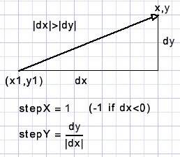
This procedure subsequently calls procedure procmove( direction) to reach pen position (x,y);
This is done by calculating values Xstep and Ystep first and then incrementing x (by Xstep) and y (by Ystep);
Difference must be made between horizontal and vertical line orientation.
 |
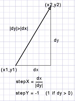 |
| horizontal orientation | vertical orientation |
Demo 3
This demo plots some lines of text.
Text is preset in array demotext together with the coordinates of the first character,
the font height and of course the character string.
Procedure startdemo(3) calls procedure painttextline(line nr) for each line of text .
Painttextline calls procedure drawdemochar(x,y) for each character of the line.
Drawdemochar finally calls movotoXY(x,y) and procmove(direction).
Remains to explain how the parameters for procedures movetoXY ( ) and procmove( ) are calculated.
A bitmap called scanmap (width=60, height=60 pixels ) is erased for each character with a black background.
Then the character is painted in scanmap with pencolor red and background white.
The black color indicates the boundaries of the character.
scanmap.
Drawdemochar has variables scanX, scanY and x, y which point to pixel positions of scanmap.
First scanX and scanY are set to 0;
Then function scanChar(var scanX,scanY) : Boolean; is called.
This function scans the scanmap (left to right, top to bottom) to find a red pixel and
return true after that red pixel is set to white.
ScanX,scanY point to the first red pixel found.
Next drawdemochar lowers the pen to set a dot.
x is set to scanX , y is set to scanY and function subscan(var x,y; var dir) : Boolean is called.
This function searches for neighbour red pixels of x,y.
If found, true is returned together with the direction code needed for the call to procedure procmove( ) to step the pen.
Also x,y coordinates are updated to reflect the last red pixel position.
If subscan returns false, scanChar is called again to continue the search
for remaining red dots, starting at scanX,scanY.
The roman font is used to paint the characters in scanmap.
The GoDemoFlag must be true for textdrawing to continue.
A click on the stop button clears the flag, ending the demo.
This concludes the HBot simulator description.

